Water Leak Under a Concrete Floor: Finding It Without Lifting the Floor
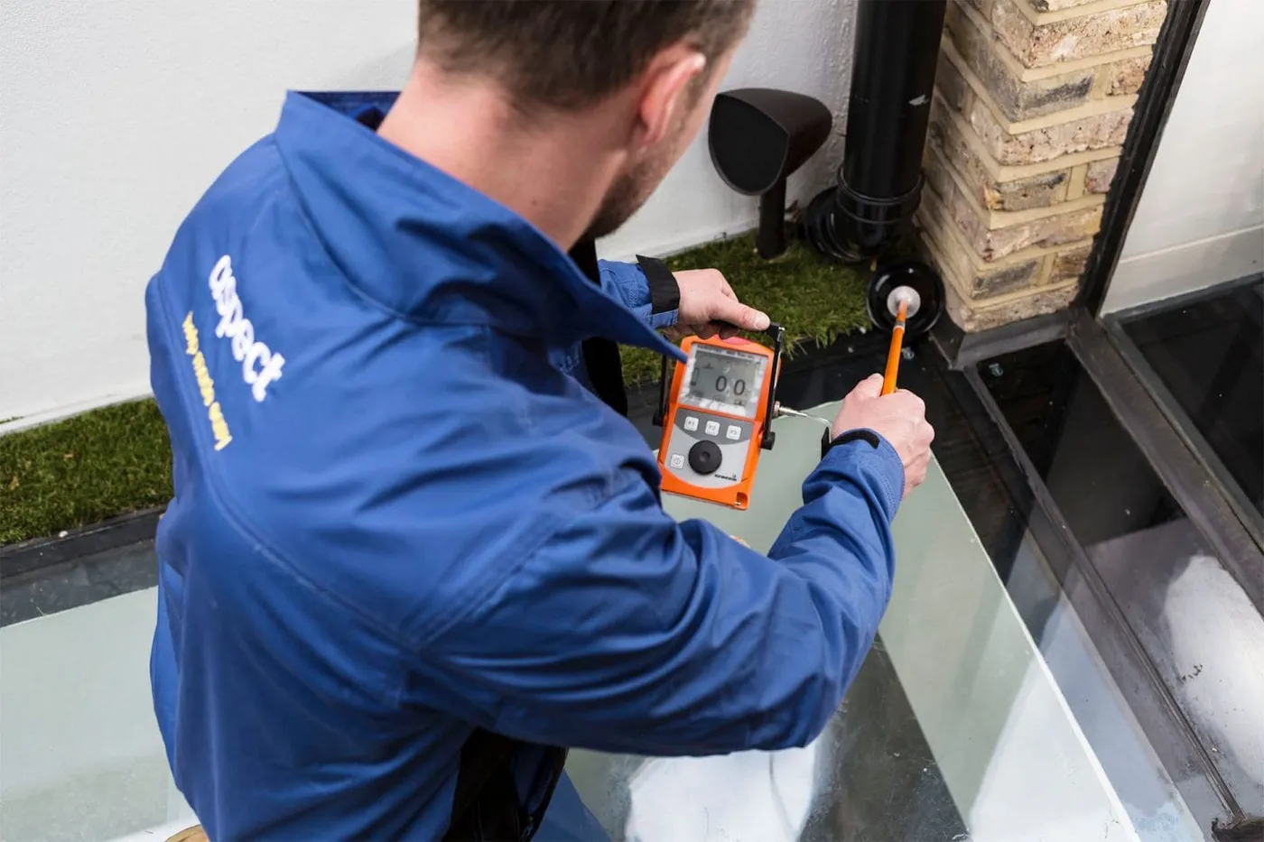
Concrete lets through heat, sound and gas, and almost nothing else. That is why under-slab detection uses the three methods it does, and why the isolation work beforehand decides how long the job takes.
Why there is pipework under your floor at all
A leak under a concrete floor sounds like a construction error until you look at how the floors were built. From the 1950s onwards, solid ground floors became the norm: a concrete slab over hardcore and a damp proof membrane, with a sand and cement screed on top to take the finish. Running services through that screed was quicker and tidier than boxing them in, so water pipes, heating flow and return, and later underfloor heating loops were laid into it as a matter of routine.
A great many solid floors in London homes therefore contain pipework, and much of it was buried without the sleeving that would let it move. Four arrangements turn up repeatedly.
- Copper heating flow and return chased into screed between rooms, often unsleeved
- Cold and hot supply pipes crossing a kitchen or hallway slab to reach a downstairs bathroom or an extension
- Continuous plastic underfloor heating loops clipped to insulation and screeded over
- The incoming supply pipe entering under the slab and rising inside the building rather than at an external wall
Each of those fails for a different reason, and the failure mode changes which detection method is worth trying first.
The signs of an under-slab leak
Under-slab leaks are quiet. The water is confined by the slab, the membrane and the ground, so it shows up as a change in the building rather than as visible water. The signs below are worth reading together rather than individually, because each one has an innocent explanation.
| Sign | What it suggests | Common innocent explanation |
|---|---|---|
| Warm area of floor that appears only when the heating runs | Escape from a hot flow or return in the screed | A buried pipe run working normally |
| Water meter creeping with every outlet closed | Loss on the pressurised supply side | A passing WC valve or a running cistern |
| Skirting, floor covering or plaster damp at low level | Water tracking up from the slab | Rising damp or a bridged damp proof course |
| Boiler pressure falling with no visible wet | A heating leak, buried or otherwise | Expansion vessel failure or repeated bleeding |
Two warnings belong here. Damp at low level is the sign most often misread, because rising damp, a bridged damp proof course and a slab leak all present the same way at skirting height. And a warm floor is not a leak by itself: a heating pipe working correctly also warms the surface above it, and the signature that matters is a patch warmer than the rest of the same run. Our article on a warm patch on the floor covers that difference.
Confirming it is a leak before anyone breaks concrete
Opening a slab is destructive, expensive and hard to undo, so the confirmation stage is where a competent survey spends its first hour. The object is to prove that water is leaving a pressurised system, then narrow which system and which section, before any instrument comes out of the van.
The isolation sequence
The sequence runs from the outside in. Start with a static meter test: every outlet closed, nothing drawn off, the meter read at the start and after a fixed interval. If the meter moves, the loss is on the supply side. Next, close the internal stopcock and repeat. If the meter still moves, the escape is upstream of the stopcock, which points at the buried supply pipe rather than at internal distribution. If it stops, the loss is inside the property.
From there, isolate branch by branch using service valves where they exist, watching the meter after each one. On the heating side the equivalent is a static pressure test from stone cold with the system off for 24 hours and, where underfloor heating is present, closing loops one at a time at the manifold until the pressure holds. That single manifold step narrows the search from an entire floor to one circuit before anybody switches a camera on.
By the end of this stage a good survey can state what has been ruled out: not the heating, or not the incoming supply, or not a pressurised system at all. Those eliminations are what make the later finding defensible, and they are the part of the report an insurer actually reads.
The three methods that work through concrete
Concrete is opaque to most of the things that make leak detection easy elsewhere. What gets through it is heat, sound and gas, and the three method families map onto exactly those.
Thermal imaging through a slab
A thermal camera reads surface temperature. Hot water escaping into a screed warms the material around it, and that warmth conducts to the surface as a plume broader and softer-edged than the pipe itself. It is fast, non-destructive, and it maps the pipe runs at the same time, which is worth having when no drawings exist.
Two constraints decide whether it is useful. There has to be a temperature difference: a hot leak, a cold leak imaged against a warmed floor, or a system cycled deliberately to create contrast. And the floor finish has to conduct. Tile and vinyl over screed image well; thick carpet, engineered timber over insulation, and a floating floor with a void beneath it can flatten the signal to nothing.
Acoustic listening and correlation
Water forced out of a pressurised pipe generates noise at the orifice, and that noise travels along the pipe wall and through the slab. Ground microphones pick it up at the surface. A correlator uses two sensors on accessible points of the same run and calculates the position of the source from the difference in arrival times, given the pipe material and the distance between them.
Correlation is the strongest tool available on a buried mains supply, because the mains runs at good pressure and the signal is strong. It weakens sharply on heating circuits, which sit at low pressure, and on plastic pipe, which damps sound rather than carrying it. A comparison of where each family earns its place is set out in our piece on acoustic, thermal and tracer gas methods.
Tracer gas under concrete
Tracer gas resolves the cases the other two cannot. The pipe is drained and a mixture of five per cent hydrogen in ninety-five per cent nitrogen is introduced. That mixture is used because at five per cent the hydrogen is non-flammable, non-toxic and non-corrosive, which makes it acceptable in pipework that will carry drinking water afterwards. Hydrogen is the smallest molecule available, so it escapes through openings that would barely weep water and migrates upward through screed, insulation and floor coverings to a detector at the surface.
It works where nothing else does: on plastic pipe, on low-pressure circuits, on very small defects, and under build-ups that defeat a thermal camera. The cost is that the system has to be taken out of service, drained, gassed, then refilled and recommissioned, so it is normally deployed once the earlier methods have narrowed the area rather than as a first move.
| Method | Best on | Blind to |
|---|---|---|
| Thermal imaging | Hot leaks under tile or vinyl on screed | Leaks under insulation, floating floors or thick carpet |
| Acoustic ground microphone | Mains pressure escapes on metal pipe | Quiet low-pressure heating leaks and plastic pipework |
| Correlation | Long buried runs with two accessible contact points | Runs of unknown material, or with fittings between the sensors |
| Tracer gas | Plastic pipe, tiny defects, difficult floor build-ups | Little, but it needs the pipe drained and out of use |
What minimal access repair actually means
Minimal access describes scale, not a promise that nothing will be broken. Where a leak has been located to a small area, the repair opens the floor at that point only: the covering is lifted locally, the screed is cut back to expose the defect, the failed section is replaced, and the area is re-screeded and made good. What has been avoided is the alternative, which is lifting a floor progressively until the water turns up.
Repair in place or reroute
Once the defect is exposed there are two options, and the right one depends on why the pipe failed. A local repair cuts out the failed section and joints in new pipe. A reroute abandons the buried length entirely and takes a new pipe on an accessible line: at skirting level, through a ceiling void, or round through an adjacent room.
The deciding question is whether the rest of the buried run has lived the same life as the piece that failed. Unsleeved copper corroding at one point in a screed has the same conditions along its whole length, and a pipe fatigued because it was never free to expand will be fatigued elsewhere too. Against that, a single puncture from a screw driven through a floor is a discrete event, and a local repair is entirely reasonable.
| Consideration | Local repair | Reroute |
|---|---|---|
| Disruption | One small area of floor opened | Surface pipework or a longer chase, but no slab work |
| Suitable when | Isolated mechanical damage or a single fitting | Corrosion, thermal fatigue, or a run that has failed before |
| Future access | New joint is buried again | Whole run becomes visible and serviceable |
One point on reinstatement. A screed patch has to cure before a covering goes back, and a floor wet for weeks has to dry before anything is laid over it or the new covering fails. Our guide to drying out after a water leak covers why those timescales run to weeks rather than days.
Where under-slab detection goes wrong
Detection under concrete narrows probability. It does not return a coordinate, and anybody promising otherwise is selling rather than surveying. Four failure modes account for most of the disappointing jobs.
The first is tracer gas surfacing away from the defect. Gas takes the path of least resistance through a slab, so it comes up through a crack, a service penetration, a slab edge or an expansion joint in preference to migrating straight up through sound concrete. A competent operator maps concentrations across the area and reads the pattern rather than declaring the first strong reading to be the answer. Where the surface is very dense, small holes are sometimes drilled to give the gas a route, which is itself minor destruction.
The second is thermal imaging on the wrong build-up. Insulation between the pipe and the surface, a floating floor with an air gap, or an underfloor heating system that warms the entire slab all remove the contrast the image depends on. The camera will still produce a picture; it just will not mean anything.
The third is acoustic work on plastic. Modern supply pipe and all underfloor heating loops are plastic, which damps the sound rather than transmitting it, and a large split can be quieter than a pinhole because the water leaves at low velocity. A quiet slab is not an empty slab.
The fourth is the assumption that wet means source. Water under a slab travels the line of least resistance in the same way gas does: along the top of the membrane, down a service duct, under a screed. The wettest place at skirting level is where the water arrived, not where it left the pipe. The same reasoning runs through our guide to finding a leak under the floor, and it is why moisture mapping supports a survey without ever concluding one.
A fifth case is worth naming because it is the most frustrating: the intermittent leak. A defect that only opens when a pipe expands under heat, or when mains pressure peaks overnight, can hold still through a full day of testing. The correct response is to say so, record what was eliminated, and test again under the conditions that provoke it, rather than break out concrete on a guess.
Underfloor heating in a slab
Underfloor heating deserves separate treatment because its geometry changes the job. A wet system is a set of continuous plastic loops running from a manifold, with no joints between the manifold and the far end of each circuit. That has one strong implication: a leak in the middle of a loop is almost always damage inflicted from above, by a screw, a nail or a core drill, rather than a fitting that has failed.
It also makes the manifold the most valuable diagnostic tool on site. Closing loops one at a time and watching the pressure narrows the search from a whole floor to a single circuit in under an hour, and costs nothing. Only then is a camera or gas worth deploying. Where the whole floor is warm, thermal imaging has little to work with, so tracer gas on an isolated drained loop is often the practical method. Our article on underfloor heating leaks covers the repair options, including the fact that a repaired joint in a screeded loop is a joint that is now buried.
Insurance, cost and what to document
Escape of water from a fixed water installation is a standard buildings insurance peril, and most policies carry a trace and access extension covering the search and the making good of damage caused by opening up. Under a slab that extension does real work, because the opening up is concrete rather than plasterboard.
Two points recur in disputed claims. The failed component is commonly excluded while the damage caused by reaching it is not, so detection, repair and reinstatement should be costed as separate lines rather than one figure. And a reroute that upgrades the installation can attract a betterment argument, which is easier to answer when the report explains why the buried run was not worth repairing. Our guide to a trace and access insurance claim sets out the sequence.
The report itself is the deliverable, and it should contain the following.
- Meter readings with the interval between them, and pressure readings before and after isolation
- Which systems were eliminated, and how
- The methods used in sequence, with the reason for moving from one to the next
- Timestamped photographs referenced to a floor sketch
- The finding expressed as a location and a cause, with the confidence attached to each
Where the cause cannot be established without exposing the pipe, the honest form of words is to say so. A report stating that the origin is confirmed beneath the hall floor but the cause is not determinable without exposure is worth more than one that guesses.
How we help with this
If the article describes a problem you actually have, these are the visits that deal with it.
- leak detection in London
Finding a hidden leak without opening the property up first.
- tracer gas leak detection
For leaks the other methods cannot reach, including buried pipework.
- underfloor heating leak detection
Loop by loop testing without lifting the whole floor.
Frequently asked questions
How do you find a water leak under a concrete floor?
In stages. First a static meter test with every outlet closed proves water is leaving a pressurised system, and closing the internal stopcock separates the buried supply pipe from internal distribution. Then one of three methods works through the concrete: thermal imaging picks up the warm plume from a hot escape, acoustic ground microphones and correlation locate noisy escapes on metal pipe, and tracer gas is introduced into the drained pipe and detected where it surfaces. The earlier isolation work is what keeps the instrument stage short.
Does the whole floor have to come up?
Not where the leak has been properly located first. Minimal access means opening the covering and screed at one small area over the defect, replacing the failed section and making good. The alternative, lifting a floor progressively until the water appears, is what detection exists to avoid. Two things still cost time: a screed patch has to cure before a covering goes back, and a slab that has been wet for weeks has to dry properly first or the new floor finish will fail over it.
Should the buried pipe be repaired or rerouted?
It depends on why it failed. A single puncture from a screw or nail driven through the floor is a discrete event, and a local repair is reasonable. Corrosion of unsleeved copper in screed, or fatigue from thermal movement in a pipe that was never free to expand, applies to the whole buried length equally, so the rest of that run has lived the same life. In those cases abandoning the buried run and taking a new accessible pipe is usually the more honest recommendation.
Why did the tracer gas point at the wrong place?
Because gas takes the path of least resistance through a slab. It will surface at a crack, a service penetration, an expansion joint or a slab edge in preference to migrating straight up through sound concrete, so a single strong reading can sit some distance from the defect. A competent operator maps concentrations across the whole area and reads the pattern rather than trusting one peak, and will say in the report where the confidence is high and where it is not.
Can thermal imaging find a cold water leak under a slab?
Sometimes, but it is much weaker than on a hot leak. The camera reads surface temperature, so it needs a contrast to work with, and cold water escaping into an already cool slab provides very little. The usual workarounds are imaging the cold patch against a floor that has been warmed by the heating, or running water through the suspect pipe at a different temperature to create a difference. Where the build-up includes insulation or a floating floor, thermal imaging is not the right tool at all.
Will insurance pay to break up the floor?
Usually, through the trace and access extension that most buildings policies carry. That extension is intended to pay for finding the source of an escape of water and for making good the damage caused by opening up, which under a slab is substantial. The failed pipe itself is commonly excluded while the damage caused by reaching it is not, so detection, repair and reinstatement should be costed as separate lines. A reroute that upgrades the installation can attract a betterment argument, which the report should pre-empt.