Leak Detection Equipment Compared: Acoustic, Correlation, Thermal Imaging and Tracer Gas
Most comparisons of leak detection methods list advantages. The useful comparison is the other one: what each instrument actually measures, what it physically cannot do, and which conditions make it produce a confident wrong answer.
What each instrument physically measures
Every argument about which leak detection method is best collapses once you separate what each instrument measures from what the surveyor wants to know. None of them detects a leak. They detect sound, temperature, gas concentration, moisture or pressure, and the leak is inferred from those measurements. Understanding which physical quantity is being sampled tells you immediately where the method will work and where it will mislead.
| Method | What the instrument actually measures | Needs the pipe pressurised? | Invasiveness |
|---|---|---|---|
| Acoustic listening | Structure-borne and ground-borne sound from water forced through a defect | Yes | None |
| Leak noise correlation | Time delay of the same leak signal arriving at two sensors | Yes | None, but needs two contact points on the pipe |
| Thermal imaging | Infrared radiated from a surface, converted to apparent surface temperature | No | None |
| Tracer gas | Concentration of an introduced gas at the surface | No, the pipe is drained | None to locate; access needed to inject |
| Moisture metering | Electrical resistance or dielectric response of a material | No | None, or pin penetration on the invasive type |
| Pressure and flow testing | Loss of pressure or continued flow in an isolated section | Yes | None |
Read that table in one direction and it explains the sequence a competent survey follows. Pressure and flow testing proves a leak exists and narrows it to a system. Acoustic, correlation and thermal narrow it to an area. Tracer gas resolves it to a point. Moisture metering maps the consequence rather than the cause, and is the instrument most often over-interpreted.
Acoustic listening: what it can and cannot do
Water escaping a pressurised pipe through a small defect generates noise across a broad frequency band. That noise travels along the pipe wall and through the water column, and radiates into the surrounding soil or structure. Acoustic leak detection uses contact microphones on fittings and valves, and ground microphones on the surface above a buried run, to find where that noise is loudest.
It is the most direct method available on a pressurised system, and on a metal pipe under reasonable pressure it is often the fastest. Three conditions govern whether it works at all.
Pressure is not optional
No pressure differential means no jet, and no jet means no noise. A drained heating circuit, a gravity waste pipe, a soil stack or an unpressurised overflow produces nothing for an acoustic instrument to find. This is the single most common reason a listening survey returns nothing on a leak that is unquestionably present. Waste and drainage leaks are not acoustic problems, and treating them as one wastes a visit.
Pipe material changes everything
Leak noise in metal pipe propagates efficiently and retains high frequency content, which is what makes it audible at distance and easy to distinguish from background. In plastic pipe, and MDPE in particular, the noise propagates largely as a fluid-borne wave, the high frequencies are attenuated quickly, and the surrounding soil couples strongly to the pipe wall. The result is a signal that is lower in frequency, quieter, and audible over a much shorter run. On a long plastic supply this is a real limitation rather than a nuisance, and it is the usual reason a survey moves to tracer gas.
Background noise sets the floor
The method is a signal to noise problem. Traffic, plant, pumps, a running appliance in an adjacent flat, or a busy London street at midday can raise the noise floor above the leak signal. Surveys on mains supplies are sometimes carried out at night for exactly this reason. Where background cannot be reduced, correlation is usually the answer, because it exploits a property of the signal that noise does not share.
Correlation: the fourth method most guides leave out
A leak noise correlator is not a louder microphone. It is a different measurement. Two sensors are attached to the pipe at accessible points either side of the suspected leak, usually at valves, hydrants or exposed fittings. The same leak signal reaches each sensor at a different time. The instrument cross-correlates the two recordings to find the time delay, and from that delay, the distance between the sensors and the speed at which sound travels in that pipe, it calculates the position of the source.
The advantage is that it is far more robust against background noise than listening, because random noise does not correlate between two sensors while the leak signal does. The disadvantage is that it depends on three inputs the surveyor has to get right.
- Two accessible contact points on the same pipe run. If the only access is one internal stopcock, correlation is not available.
- An accurate distance between them. An error in the measured length becomes an error in the calculated position.
- An accurate propagation velocity. This depends on the pipe material, its diameter and its wall thickness. On a known metal pipe the standard figures are reliable; on plastic, or on a run of unknown or mixed material, the velocity has to be determined on site, and a wrong assumption puts the calculated point in the wrong place with complete confidence.
That last point is the honest caveat about correlation and it is rarely stated. The instrument will always produce an answer. Whether the answer is right depends on whether the pipe is what the surveyor assumed it was. On London's older supplies, where a run can change from lead to copper to MDPE across three repairs, that assumption deserves checking rather than making.
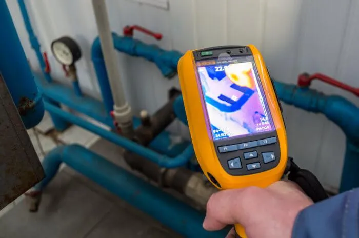
Thermal imaging: what the camera is actually seeing
A thermal camera measures infrared radiated from a surface and converts it into an apparent surface temperature. It does not see water, it does not see pipes, and it does not see through anything. What it detects is the thermal consequence of water on or behind a surface: a heating leak warming a floor, or evaporation from a damp patch cooling a wall relative to its dry surroundings.
Used correctly, thermal imaging is the fastest way to narrow a large area to a small one, and it is unmatched on underfloor heating, where the whole point is a deliberate temperature difference between the circuit and the screed. Its limitations are all versions of the same limitation.
No differential, no image
The camera needs a temperature difference to render. Cold water leaking into a cold void in an unheated room in October produces a thermogram indistinguishable from a dry one. This is why a survey often runs the heating or the hot supply deliberately before imaging, and why a leak that has stopped and dried before the visit may be invisible.
Emissivity and reflection produce confident errors
Different materials radiate differently at the same physical temperature, and shiny surfaces reflect the thermal environment rather than reporting their own state. A stainless splashback, gloss paint, a radiator reflected in a floor tile and a thermal bridge at a wall junction all produce features that look like findings. Every one of them is a false positive, and the discipline that separates a survey from a photograph is ruling them out before reporting them.
Tracer gas: when the others have failed
Tracer gas is the method of last resort and, for that reason, the one that resolves the cases the others cannot. The pipe or circuit is drained, and a gas mixture is introduced under pressure, typically around 5 per cent hydrogen in 95 per cent nitrogen, which is non-flammable at that concentration and harmless to the system. Hydrogen is the smallest molecule there is. It escapes through defects too small to pass a measurable quantity of water, diffuses through screed, soil, tile grout and floor coverings, and rises. A sensitive detector is then used at the surface to find where the concentration peaks.
The reasons tracer gas succeeds where acoustic and thermal fail are structural rather than incidental.
- It does not require the system to be pressurised with water, so it works on waste, drainage and drained heating circuits.
- It does not require a temperature differential, so ambient conditions are irrelevant.
- It is largely indifferent to pipe material, which removes the plastic pipe problem that limits acoustic work.
- It works under concrete, screed and hard landscaping, where acoustic signal is attenuated and thermal sees only the surface.
The constraints are practical. The system has to be drained and isolated, which takes time and is not always possible in occupied premises without disruption. Injection requires a physical access point. And a sealed surface such as an impermeable membrane or a fully grouted and sealed tiled floor can delay or divert the gas, so the detected surface peak is not always directly above the defect. A careful survey samples a grid rather than accepting the first reading.
Pipe material, pressure and depth: the constraints that decide
The method is chosen by the conditions, not by preference. This is the table most comparisons of leak detection equipment do not build, and it is the one that answers the question people are actually asking.
| Condition | Acoustic | Correlation | Thermal | Tracer gas |
|---|---|---|---|---|
| Copper or steel, pressurised | Strong | Strong | Useful if a differential exists | Strong |
| MDPE or plastic, pressurised | Limited range | Workable if velocity is measured on site | Useful if a differential exists | Strong |
| Unpressurised waste or drainage | Not applicable | Not applicable | Sometimes, via evaporative cooling | Strong |
| Under concrete slab or screed | Attenuated | Workable with contact points | Surface effects only | Strong |
| Underfloor heating circuit | Weak | Weak | Strong | Strong, once drained |
| Deeply buried external main | Depends on depth and soil | Strong with two access points | Rarely useful at depth | Strong |
| High background noise | Poor | Strong | Unaffected | Unaffected |
Two entries in that table are worth reading twice. Acoustic methods are not a general purpose tool: they are a pressurised metal pipe tool that degrades as you move away from those conditions. And tracer gas is strong almost everywhere, which is precisely why it is not the first method used. It requires draining, isolation and access, so it is deployed once cheaper methods have narrowed the problem or have failed to.
Where each method produces a false positive
Every instrument in this field will report something. The question a survey has to answer is whether the something is the leak. These are the failure modes that produce a confident wrong answer, and how each is excluded.
| Method | Common false positive | How it is ruled out |
|---|---|---|
| Acoustic | A partially closed valve, a running cistern or a pump generating pipe noise | Isolate and repeat; close off appliances and re-listen |
| Acoustic | Noise transmitted along a pipe from a leak elsewhere on the run | Compare amplitude at several contact points; correlate |
| Correlation | Wrong propagation velocity from an assumed pipe material | Determine velocity on site; verify the calculated point by listening |
| Thermal | Thermal bridging at a junction, lintel or joist | Compare against the building's construction; check for a matching moisture reading |
| Thermal | Reflection from a shiny surface, or an emissivity difference between materials | Image from a second angle; adjust for the material |
| Thermal | Residual damp from a leak that has already stopped | Re-image after a dry interval; correlate with meter readings and use |
| Tracer gas | Gas tracking along a service duct or under a membrane to a remote exit | Grid sample rather than accept the first peak; confirm against pipe route |
| Moisture meter | Salts, foil-backed plasterboard or metal behind the surface reading as damp | Cross-check with a second instrument type; take a depth reading |
Two of those deserve emphasis because they account for most misdiagnoses. A surface moisture reading tells you the surface is wet; it does not tell you where the water came from, and a high reading beside a cold external wall in February is a condensation candidate until proved otherwise. And a thermal anomaly without a corroborating moisture reading is an observation, not a finding. Our guide to telling damp from a leak sets out the environmental readings that separate the two.
How the methods are sequenced on a real survey
No single instrument answers the question, and a survey that leads with its favourite tool is guessing with equipment. The sequence that holds up is elimination first, location second.
- Establish that there is a loss, and from which system. A timed meter test with all outlets closed establishes whether water is leaving the supply. The heating circuit is isolated and its pressure watched separately, because a falling boiler gauge is as often a failed expansion vessel or a discharging pressure relief valve as it is a leak.
- Map the consequence. Moisture readings across the affected area, at depth where the finish allows, with ambient temperature and relative humidity recorded. This defines the extent and gives the later finding something to be consistent with.
- Narrow the area. Thermal imaging where a usable differential exists; acoustic listening on a pressurised run; correlation where background noise or pipe length defeats listening.
- Resolve to a point. Tracer gas where the previous stages have narrowed the area but not the position, or where the system is unpressurised or the pipe material has defeated acoustic work.
- Verify before opening up. Confirm the located point by a second, independent means wherever the access cost is significant. The cost of one more reading is always lower than the cost of the wrong excavation.
The eliminations from the first two stages are not preliminaries to be skipped in a report; they are what makes the final finding defensible to a loss adjuster or a leaseholder. A report stating that the mains supply was eliminated because the meter was static over a measured interval with all outlets closed is evidence. One stating that a leak was found in the kitchen is an assertion. The Financial Ombudsman Service makes the same point in its guidance on underground pipe claims, where it expects a report to carry enough detail to understand the condition of the pipe and a diagram showing the layout of the pipework around the building, rather than a summary. Our overview of leak detection technology covers the equipment in more depth, and the survey process itself is set out in our guide to leak detection.
How we help with this
If the article describes a problem you actually have, these are the visits that deal with it.
- thermal imaging surveys
Infrared showing where warm or cold water tracks behind a surface.
- tracer gas leak detection
For leaks the other methods cannot reach, including buried pipework.
- acoustic leak detection
Ground microphones and correlators on a pressurised pipe.
Frequently asked questions
Which leak detection method is the most accurate?
The question does not have a single answer, because accuracy depends on the conditions rather than on the instrument. Correlation can locate a leak on a pressurised run precisely, but only where two contact points exist and the propagation velocity for that pipe is known or measured. Tracer gas resolves to a small surface area almost regardless of pipe material or pressure, but requires the system to be drained. Thermal imaging narrows an area quickly but needs a temperature differential. A survey that uses one method alone is accepting the limits of that method.
Why can acoustic leak detection not find a drain or waste leak?
Because there is no pressure. Acoustic methods detect the noise generated by water being forced through a defect under pressure, and a gravity waste pipe, soil stack or overflow produces no such jet and therefore no signal. This is the most common reason a listening survey returns nothing on a leak that is definitely present. Unpressurised systems are investigated with tracer gas, with a drain camera survey, or with dye tracing, none of which depend on the pipe being pressurised.
Does thermal imaging see through walls?
No. A thermal camera measures infrared radiated from a surface and converts it to an apparent surface temperature. It detects the thermal consequence of water behind a surface, such as a warmed floor above a heating leak or a wall cooled by evaporation, but it never images the pipe or the water itself. It also needs a temperature difference to render anything, which is why a leak that has stopped and dried before the survey may produce no image at all.
Is tracer gas safe to use in an occupied property?
The mixture normally used is around 5 per cent hydrogen in 95 per cent nitrogen, which is non-flammable at that concentration and is not harmful to the plumbing system. The practical constraints are logistical rather than safety related: the pipe or circuit has to be drained and isolated before the gas is introduced, an access point is needed for injection, and both of those can be disruptive in an occupied home. That is why tracer gas is usually deployed after cheaper methods have narrowed the search.
Why does a plastic water pipe make acoustic detection harder?
Leak noise in metal pipe propagates efficiently and keeps its high frequency content, which makes it audible at a distance and easy to distinguish from background. In plastic pipe, and MDPE in particular, the noise travels largely as a fluid-borne wave, the high frequencies attenuate quickly and the surrounding soil couples strongly to the pipe wall. The signal is quieter, lower in frequency and audible over a much shorter run, so listening range drops sharply and correlation or tracer gas usually becomes the better option.
What is a leak noise correlator and when is it used?
It is an instrument that attaches two sensors to a pipe either side of a suspected leak, records the same leak signal at both, and calculates the time delay between them. From that delay, the distance between the sensors and the speed of sound in that pipe, it computes the leak position. Because random background noise does not correlate between two sensors while the leak signal does, correlation works in conditions where plain listening fails, such as a busy street or a building with running plant.